
HIRES Graphics on Apple II
The Apple II was innovative in many ways. One of its most remarkable feats was that it was the very first home computer supporting color graphics! Think about it! While all its competitor could display 40 to 64 columns of ASCII characters, the Apple II could displays graphics with up to 16 colors in LoRes mode and 6 colors in HiRes mode! This was huge!
Now that I know how to program my Apple II in C and ASM, I could not resist trying to display a high resolution image on my screen! So I added a Title Screen to my Game of Life 😉
This article is the third concerning my port of Conway’s Game of life on the Apple II. Here are the two previous ones:
Graphics modes
Information can be display be the Apple II using different graphic modes.
- TEXT mode allows to display 24 rows of 40 ASCII characters. With an expansion board, displaying 80 characters becomes possible.
- LORES mode is 40 pixel wide, 48 pixel tall in 16 colors! While it seems quite low by today’s standards, it is reasonably fast and straightforward to program for. This is the mode used to edit the “play-field”, then watch the cells evolve, in my port of the Game of Life.
- HIRES is the mode used by most graphical programs and games at the time. It is 140 pixel wide, 192 pixel tall in 6 colors. BUT… relying on many oddities, it is not as easy to grasp nor program for than the LORES mode. More precisions later.
- MIXED mode allow to use the bottom of the screen of LORES and HIRES mode to display four lines of text.
- Later Apple II models came with the so called DOUBLE LORES and the DOUBLE HIRES mode. The later was quite difficult to program for and heavily taxing memory. So it was mainly used for static screens.
From that point, I will be exclusively writing about HIRES.
HIRES Oddities
Color is achieved a very peculiar way on an Apple II. Furthermore, Woz made the choice to reduce the number of chips to the minimum. The price paid being that programming HIRES graphics on the Apple II is not as easy and fast that it could be on other machines.
Producing colors with black & white dots!
At its core, the Apple II is a black and white machine!
On the contrary to other 8 bit and 16 bit machines, you don’t select colors in a palette. Instead, you have to carefully place black and white dots. Indeed, the hardware was designed so that a rapid succession of such points introduces interferences into the color carrier of the signal sent to the NTSC TV.
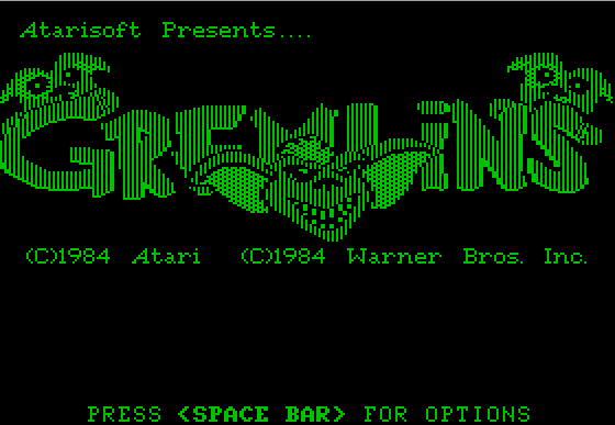 Image seen on a black & white set
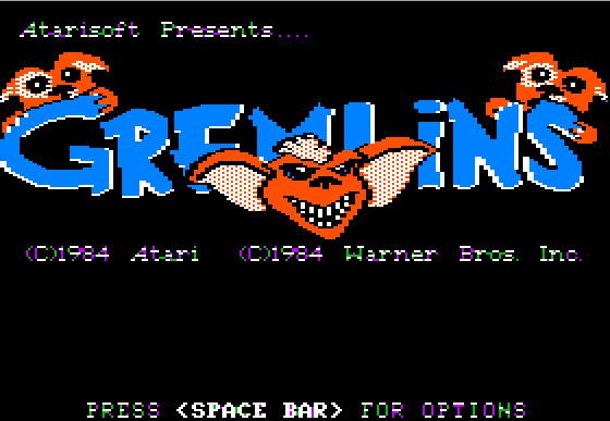 The same image on a color NTSC set
If you watch carefully the two images above you can notice:
- That the text in the color version is not very crisp and is affected by some color fringes. Those are the “interferences” in action!
- That the black & white version seems to be twice the resolution. And it is indeed! In order to achieve the 140 colored pixels of an HIRES line, you’ve got to draw 280 black and white dots!
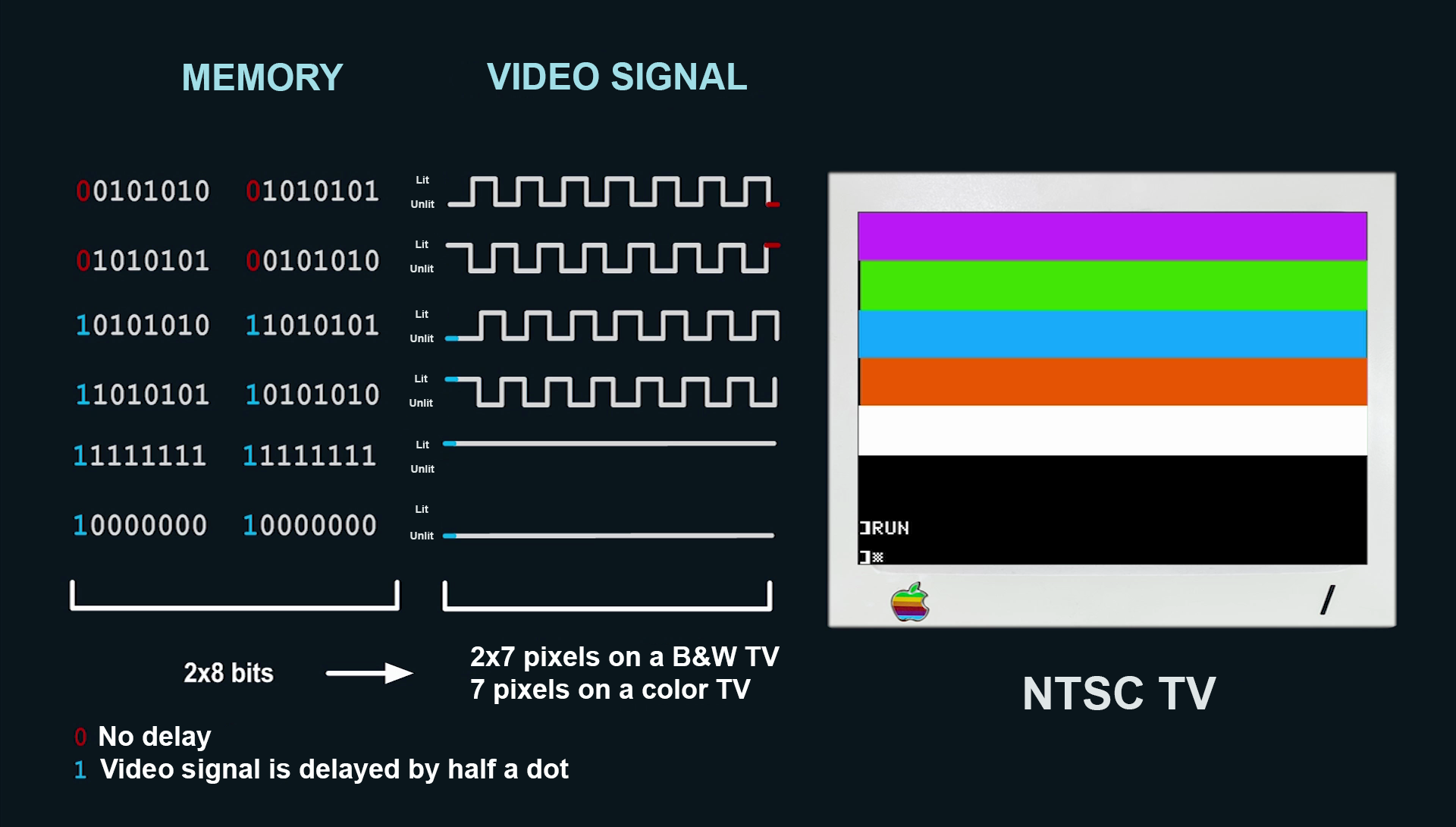
Sending a succession of lit dots followed by unlit dots will draw color pixels, while two consecutive white dots will result in a white pixel and two consecutive black dots produce a black pixel. If you’re not already lost, wait, there is more!
The process I just described only allows you to produce four colors: WHITE, BLACK, GREEN and PURPLE. So how can the system also produce BLUE and ORANGE?? By delaying the signal of half a dot!
 Color generation on the Apple II
In memory
Pages
Two memory blocks can be read by the graphic circuitry of the machine in order to display a HIRES picture.
- PAGE 1, from 0x2000 to 0x3FFF
- PAGE 2, from 0x4000 to 0x5FFF
Layout
7 dot blocks
Each page allows the description of 192 lines of 140 pixels, or 280 dots. Those dots are grouped into lines of 40 blocks of 7 dots. Each of these dot is controlled by one bit: 0 produces an black dot, while 1 produces a white dot. Such a 7 dot block is described by one byte.
And the 8th bit? It controls the half-dot delay applied, thus the COLOR GROUP of the block.
- 8th bit = 0 : GROUP 1, allowing to display GREEN, VIOLET, BLACK and WHITE
- 8th bit = 1 : GROUP 2, allowing to display ORANGE, BLUE, BLACK and WHITE
This 8th bit is the higher bit of the byte.
The 7 other bits describe the dots in the following order: the lesser bit corresponds to the dot displayed on the left and the higher bit to the dot on the right.
Those bytes are grouped inside 40 block lines and addressed the following way: the byte of lowest address corresponds to the left-most block of one line, while the byte of highest address correspond to the block on the right.
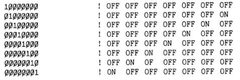 Dots layout in a byte
If you followed carefully, you surely noticed that the layout of the bits inside one byte (7 dot block) is the reverse of the layout of the bytes inside a line! Legends tell that this insanity allowed Woz to save two chips…
Colors
If you want to produce color, you have to set the high bit accordingly to the colors you want to produce.
Then you have to lay the dots following these directives:
- dots OFF ON gives GREEN (GROUP1) or ORANGE (GROUP2)
- dots ON OFF gives VIOLET (GROUP1) or BLUE (GROUP2)
- dots ON ON gives WHITE
- dots OFF OFF gives BLACK
As 7 dots gives 3.5 colored pixels, you’ll often have to think about the layout of two consecutive blocks.
To sum those things up, here are the bytes required to obtain a line of 14 green pixels:
0x2A – 0x55 – 0x2A – 0x55
10 10 10 – 10 10 10 1 – 10 10 10 – 10 10 10 1
(the colored bits describe adjacent dots)
Clashing
Now, two limitations become evident:
- You cannot display a color from GROUP 1 and a color from GROUP 2 within the same 7 dot block.
- Two different adjacent colors may lead to the appearance of unwanted artifacts! Indeed if you want to display GREEN (dots: OFF ON) followed by VIOLET (dots: ON OFF), there will be two adjacent ON dots, leading to the appearance of WHITE!
Those artifacts were called clashing back in the days. Quoting Wikipedia:
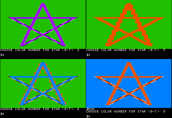 The horizontal borders between two colors generate “fringe effects” on the Apple II. In the lower left image, drawing a blue star on a green background causes the Apple II to add black, white and orange pixels at and near the horizontal boundaries between the green and blue.
Interleaving
One more thing…
The lines are not contiguous in memory! Meaning line number 2’s address does not follow line number 1’s… Instead, they are ordered according to a 64 line interleaving pattern.
Below lies a table from the Apple’s documentation of the time.
On the left are the address of so-called “boxes” of height lines. On the right, in the zoomed view, you have the offset to be applied for each line inside a box. For instance, line #10 is the second line of the second box. Therefore, its address is 0X2480.
On the top are the offset of each 7 dot blocks inside a line. Therefore, the block #3 of line #10 lies at the address 0x2483.
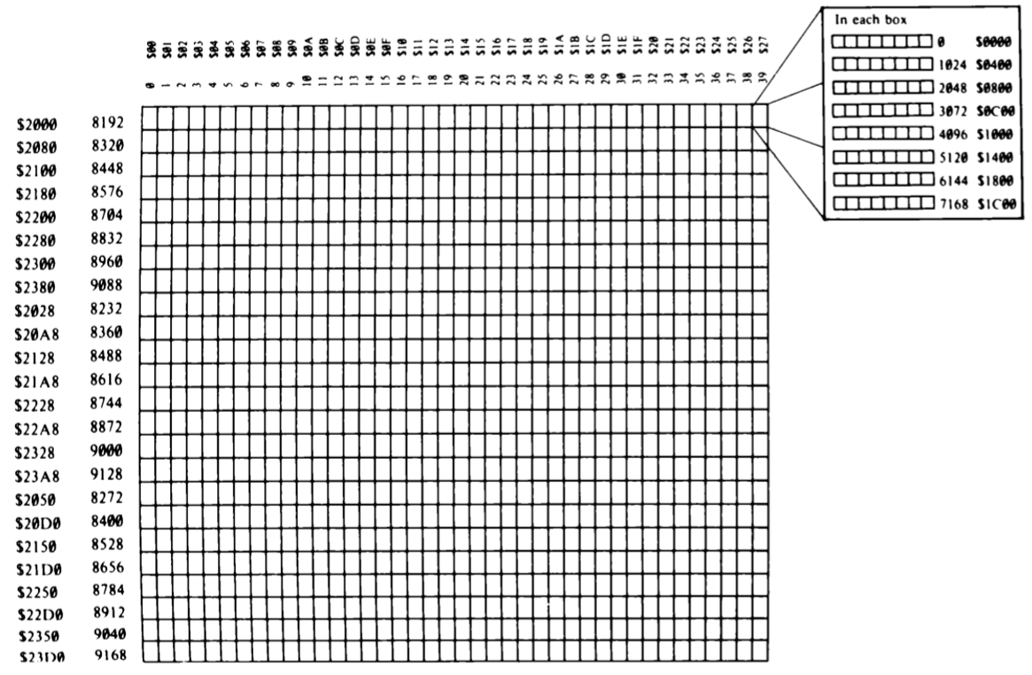 Starting address of the ordered lines
Holes
And a last, the PAGES are 8192 byte long, but 192*40 = 7680! 512 bytes are missing!
Those bytes are 8 byte long holes located at the end of every line which address ends with 0x50 or 0xD0. In the eighties, code wizards did not left these holes unused! For instance, this memory could be used to host the code of a self displaying image!
Soft-switches
In order to display your image, you have to activate some soft-switches by reading or writing to the following addresses:
- 0xC050 in order to switch to the graphical display
- 0xC052 to be full-screen
- 0xC057 to enter HIRES mode
- 0xC054 to select PAGE 1 or 0xC055 to select PAGE 2
In order to display elaborate animations, you can work on a PAGE while the other one is displayed. Yes, the Apple II can perform double buffering!
Rgb2HiRes
Remember that I wanted to add a Title Screen to my Game of Life. But it is now apparent that producing a HIRES image is not a very straightforward task. Thus, I found it faster and easier to program a tool converting a modern RBG image (PNG, JPEG, etc) into a proper binary file that only need to be loaded in PAGE 1 or PAGE 2 in order to be displayed!
I called this program Rgb2Hires 😉
You can get it on Github.
Of course it’s not magical: you’ve got to respect the caveats exposed before.
In particular, your source image must be only composed of Black, White, Purple, Orange and Blue pixels.
And it has to be 140×192 pixels. Remember that HIRES pixels are anamorphic: they are not square, but twice wider than tall! For easy drawing, Photoshop or equivalent programs can be told to work on non-square pixels. In Photoshop, this option can be found in View / Pixel Aspect Ratio. Thus the image in the editor will appear with the same proportion that on the Apple II.
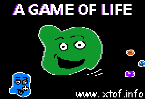 Game of Life’s Title Screen, PNG exported from Photoshop
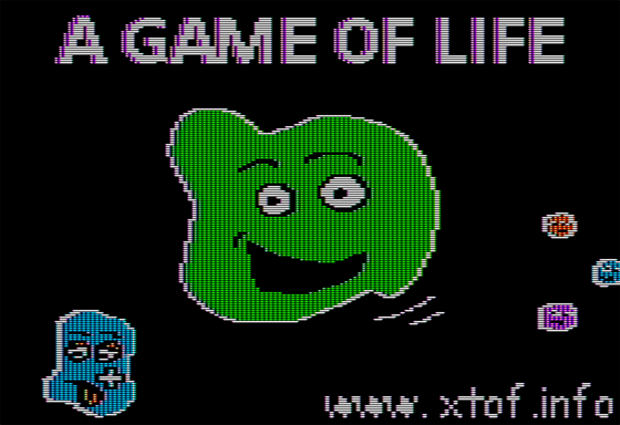 Game of Life’s Title Screen, HIRES image in AppleWin